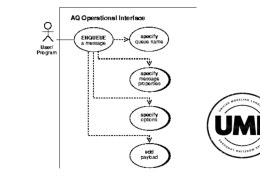
A Use Case Diagram in Unified Modeling Language (UML) visually represents the interactions between users (actors) and a system, showcasing the system’s functionalities from a user perspective. It helps in understanding system requirements and identifying primary interactions.
Components:
1. Actors: External entities (users or other systems) interacting with the system.
2. Use Cases: Specific functionalities or services provided by the system.
3. System Boundary: Defines the scope of the system.
4. Relationships:
– Association: Connects actors to use cases.
– Include: Represents mandatory use case inclusion.
– Extend: Represents optional or conditional use case extensions.
Example:
In an online shopping system, actors could be Customer and Admin. Use cases might include Place Order, View Product, and Manage Inventory.
Uses:
– Requirements Analysis: Identifies system requirements from user interactions.
– System Design: Aids in planning the system’s functionality.
Use case diagrams provide a clear, user-centric view of system operations, essential for stakeholders and developers.

